Ochrana proti podbití/přebití článků - uživatelsky nastavitelné hranice napětí pro sepnutí odpojovacích relé výstupů.
Umožňuje monitoring článků s nejvyšším /nejnižším napětím (napětí, číslo článku)
Velmi nízká vlastní spotřeba, zabudovaná funkce nouzového sebevypnutí při podbití
podpora širokého spektra běžně dostupných modulů a komponent pro rozšíření funkčnosti
Specifikace:
Podporuje připojení 4 až 16 LiFePO4 nebo 5 až 16 LTO článků (a libovolný jiný počet v tomto rozsahu)
Pro odpojení při nouzových stavech lze řídit jednocívková relé (stykače) nebo bistabilní relé (odpojení nabíječek, zátěže, ...)
Kompatibilní s mnoha monitorovacími systémy - Arduino, Raspberry, LAN Controller, Siemens LOGO PLCs, Schneider Zelio PLC module, Eaton Easy PLC, TECO Foxtrott PLC, a další
Plně uživatelsky konfigurovatelné (Umin, Umax, ...)
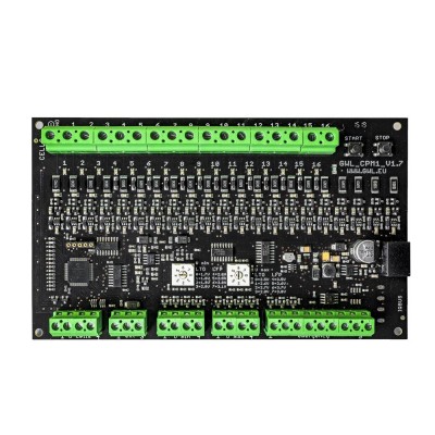
Popis základních částí elektronické desky
INPUTS - inputs terminal for connecting 16 pcs battery cells
BUTTONS - press more then 2 second for ON or OFF
SIGNAL LEDS - signal leds show which cell has nimumum and maximum voltage
VOLTAGE SELECTORS - with this trimmers it is possible to set Umax and Umin
OUTPUTS - using outputs terminals it is possible to control other devices and power relays.
Základní zapojení:
BATTERY – Connect the battery to GND and CELLS inputs 1–16. GND is always negative (-) of the entire battery. Connect the positive (+) poles of each battery cell to inputs 1–16 in the electrical order from GND as they are connected in series.
Ucells – Connect digital voltmeters (not analogue with pointers), bargraphs, or use for communication with a connected device. Use only the high impedance load and follow the principles of safe connection to the connected systems described in the ‘Installation procedure and safe wiring principles’ section.
Umin – Use to open the load relay or for optical and sound indication of low battery cell voltage or to communicate with the connected system.
Umax – Use to open the charger relay or for optical and sound indication of high battery cell voltage or to communicate with the connected system.
Emergency 1, 2, 3 – Use for emergency battery disconnection.
Emergency 4–9 – Use to control the module by pulse switching (> 300ms, start, stop, reset). If inputs 4 + 5 are permanently connected, the module does not respond to commands via outputs 6, 7 and 8, 9.